A 5-way switch is a crucial component in electrical systems, particularly in guitars and lighting. It allows multiple circuit paths, offering flexibility and control. The wiring diagram is essential for installation and troubleshooting, providing a clear guide for safe and effective setup.

Understanding the Basics of a 5-Way Switch
A 5-way switch is a crucial component in electrical systems, commonly used in guitars and lighting. It allows multiple circuit paths, enabling flexible control over pickups or lights. Understanding its wiring is essential for installation and troubleshooting.
What is a 5-Way Switch?
A 5-way switch is a versatile electrical component designed to control multiple circuit paths. Commonly used in guitars and lighting systems, it enables the selection of different configurations or connections. The switch typically features five terminals, allowing for various combinations of power distribution. In guitars, it is often used to select between pickups, while in lighting, it can control multiple fixtures or zones. The 5-way switch is prized for its flexibility and durability, making it a popular choice for both DIY projects and professional installations. Understanding its operation is essential for effective wiring and troubleshooting. Whether for musical instruments or electrical systems, the 5-way switch provides a reliable solution for managing complex connections.
Importance of Wiring Diagrams
Wiring diagrams are essential for the safe and accurate installation of a 5-way switch. They provide a visual representation of the connections, making it easier to understand how the switch interacts with other components. Whether you’re working on a guitar or a lighting system, a wiring diagram ensures that the circuit is set up correctly, reducing the risk of short circuits or electrical hazards.
These diagrams are particularly useful for beginners, as they break down complex connections into manageable steps. They also serve as a troubleshooting guide, helping to identify and repair issues quickly. By following a wiring diagram, you can avoid guesswork and ensure that your project functions as intended. This makes diagrams indispensable for both DIY enthusiasts and professional electricians.

Additionally, wiring diagrams save time by providing a clear roadmap for the installation process. They are widely available, including in PDF format, making it easy to access and print them for reference. Overall, a wiring diagram is a crucial tool for achieving a successful and reliable 5-way switch installation.
Key Components of a 5-Way Switch
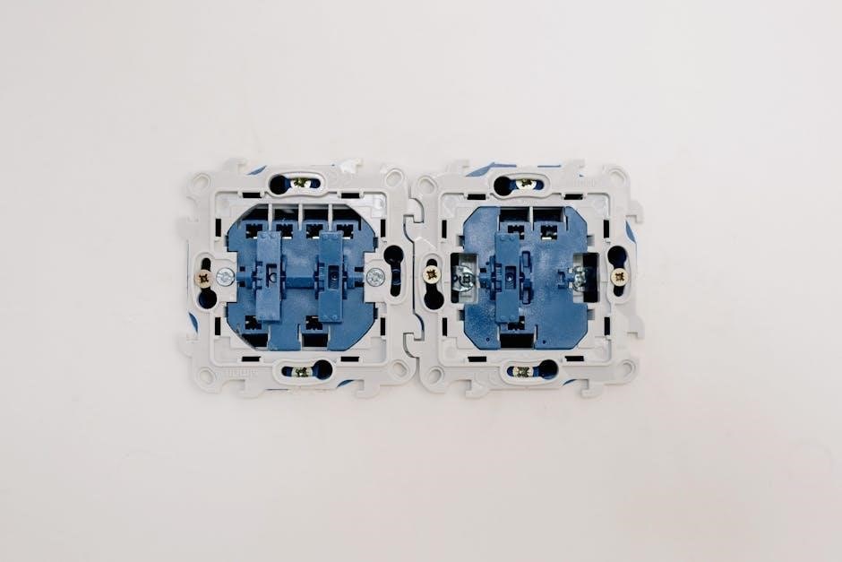
A 5-way switch consists of several critical components that ensure its functionality. The switch features multiple poles, which are the conductive parts that make or break the electrical connections. These poles are connected to terminals, where wires are attached to create the necessary circuits. The actuator is the part of the switch that is moved to change the circuit configuration, typically a lever or button. Some switches also include an insulating body to prevent electrical shock and ensure safe operation;
Understanding these components is vital for proper wiring and installation. The terminals are labeled to indicate their function, such as “input,” “output,” or “common.” The switch’s design allows it to handle multiple circuits simultaneously, making it versatile for various applications. Proper connection of these components ensures reliable performance and safety in electrical systems.

Types of 5-Way Switches
5-way switches come in various types, including single-pole, double-pole, and three-pole configurations; They are widely used in both residential and commercial settings for controlling multiple lights or electrical components. These switches offer flexibility and versatility in wiring setups, making them suitable for complex electrical systems. Understanding the differences between these types is crucial for selecting the right switch for your specific needs. Wiring diagrams are essential for proper installation and troubleshooting, ensuring safe and efficient operation of the switch in any setup.
Single-Pole vs. Double-Pole Switches
A single-pole switch controls a single circuit, connecting or disconnecting power from one source. It has two terminals: one for the incoming “hot” wire and one for the outgoing wire to the load. This type is ideal for simple on/off applications. In contrast, a double-pole switch controls two separate circuits, handling two live wires simultaneously. It has four terminals: two for the incoming hot wires and two for the outgoing wires. Double-pole switches are commonly used in higher voltage or current applications, such as controlling two lights or circuits independently. Both types are essential in electrical systems, but the choice depends on the complexity and requirements of the setup. Understanding the differences is crucial for selecting the right switch and ensuring proper wiring, as outlined in a 5-way switch wiring diagram.
Three-Pole Switches
A three-pole switch is designed to control three separate circuits simultaneously, making it highly versatile for complex electrical setups. It features six terminals: three for incoming “hot” wires and three for outgoing connections. This switch is ideal for applications requiring multiple independent controls, such as managing three different lights or devices from a single location. The three-pole switch is commonly used in industrial or large-scale residential settings where advanced control over multiple circuits is necessary. Proper wiring is essential to ensure safe and efficient operation. A 5-way switch wiring diagram often includes configurations for three-pole switches, providing detailed instructions for connecting wires to each terminal. This ensures that each circuit is isolated and functions correctly without interference. Understanding the wiring process for a three-pole switch enhances the overall functionality and safety of electrical systems, making it a valuable skill for both professionals and DIY enthusiasts.
Specialty Switches
Specialty switches are designed for specific applications, offering unique functionalities beyond standard switches. In guitar wiring, for example, a 5-way switch is often used to select different pickup combinations, enhancing tonal versatility. These switches are available in various configurations, such as Fender-style or import models, each with distinct wiring requirements. A 5-way switch wiring diagram is essential for understanding how to connect pickups, tone controls, and output jacks. Specialty switches may also include features like coil-splitting or phase options, requiring precise wiring to achieve desired effects. For custom setups, such as HSH (humbucker-single-humbucker) configurations, a detailed wiring diagram ensures proper installation. Whether for musical instruments or advanced lighting systems, specialty switches offer tailored solutions, making them indispensable for unique electrical needs. Always refer to a reliable PDF wiring diagram to guide the installation process accurately.

Installation Guide for a 5-Way Switch
This guide provides step-by-step instructions for installing a 5-way switch, ensuring safe and proper connections. Prepare tools, follow diagrams, and test the circuit to confirm functionality. Always refer to a wiring diagram for accuracy.
Preparing for Installation
Before installing a 5-way switch, gather essential tools like screwdrivers, wire strippers, and pliers. Ensure you have insulated wire, connectors, and a voltage tester. Shut off power at the circuit breaker to ensure safety. Review the wiring diagram to understand connections and plan the layout. Identify the switch terminals and corresponding wires to avoid confusion. Use wire nuts or solder for secure connections. Double-check local electrical codes for compliance. Proper preparation ensures a smooth and safe installation process, minimizing errors and potential hazards. Always prioritize safety by disconnecting power and verifying circuit deactivation before starting work. Consulting the wiring diagram repeatedly will help maintain accuracy and confidence throughout the process.
Step-by-Step Wiring Instructions
Begin by connecting the power supply to the common terminal on the 5-way switch. Use insulated wire for safety and durability; Next, identify the output terminals and connect them to the respective loads or devices; Ensure secure connections using wire nuts or solder. Refer to the wiring diagram to match each wire correctly. For multiple circuits, connect the traveller wires between switches. Double-check all connections to prevent short circuits. Use a voltage tester to verify live wires before handling. Finally, test the switch by toggling through each position to ensure all circuits function correctly. Properly label each connection for future reference. If unsure, consult the wiring diagram or seek professional assistance. This method ensures a reliable and safe electrical setup.
Testing the Circuit

After completing the wiring, test the circuit to ensure proper functionality. Use a multimeter to verify continuity and voltage at each terminal. Start by turning off the power supply and checking for short circuits. Once confirmed safe, turn the power on and test each switch position to ensure all connected devices operate correctly. Verify that each load turns on and off as intended, and check for any unexpected behavior. If a device fails to activate, review the wiring connections and consult the wiring diagram for accuracy. Pay attention to any flickering lights or unusual sounds, which may indicate loose connections. If issues persist, consider consulting a professional electrician. Proper testing ensures the circuit operates safely and efficiently, providing reliable control over your electrical system.

Troubleshooting Common Issues
Identify wiring errors, intermittent connections, or short circuits. Use a multimeter to verify continuity and voltage. Consult the wiring diagram to trace connections; Address loose wires and incorrect terminal placements for reliable operation.
Identifying Wiring Errors
Wiring errors are common but can be identified systematically. First, verify all connections against the 5-way switch wiring diagram. Ensure terminals are correctly matched. Check for loose wires, which can cause intermittent issues. Use a multimeter to test continuity and voltage drop. If the switch fails to control circuits as expected, inspect for short circuits or incorrect terminal pairings. Review the wiring diagram to confirm the proper sequence of connections. Pay attention to ground wires, ensuring they are securely attached to prevent faulty operation. Addressing these issues methodically helps resolve problems efficiently and ensures the switch functions as intended. Always refer back to the wiring diagram for accurate troubleshooting guidance.
Fixing Intermittent Connections
Intermittent connections can be frustrating and challenging to diagnose. Begin by inspecting the wires and terminals for signs of wear, corrosion, or loose connections. Use a multimeter to test for continuity and identify any breaks in the circuit. Refer to the 5-way switch wiring diagram to ensure all connections are correctly paired. Clean or replace corroded terminals, and tighten any loose screws or clips. If a wire is damaged, splice in a new section or replace it entirely. Apply solder to secure connections and prevent future issues. For switches with moving parts, ensure they are properly aligned and lubricated if necessary. Environmental factors like temperature changes or vibration can also cause intermittent issues, so consider using heat-resistant or vibration-proof materials. Addressing these problems systematically will restore reliability to your electrical system. Always consult the wiring diagram to confirm the correct configuration before making repairs.
Resolving Short Circuits
Resolving short circuits in a 5-way switch setup requires careful identification and correction. Begin by disconnecting the power supply to ensure safety. Use a multimeter to test for shorts between wires or terminals. Refer to the wiring diagram to verify proper connections and identify mismatches. Common causes include incorrect wire connections, damaged insulation, or faulty terminals. Inspect the wires for signs of fraying or burns, and replace any compromised sections. Ensure all connections are secure and properly insulated to prevent unintended contact. If a terminal is corroded or bent, clean or replace it as needed. Double-check the wiring diagram to confirm the correct configuration before restoring power. Regularly inspecting the circuit and maintaining clean connections can help prevent future short circuits. Addressing these issues promptly ensures the system operates safely and efficiently, avoiding potential damage to the switch or connected components.

Safety Tips and Precautions
Always turn off power before working on a 5-way switch. Use insulated tools to prevent shocks. Follow the wiring diagram carefully to avoid misconnections. Test the circuit with a multimeter before restoring power for safety.
Working with Live Circuits
When working with live circuits, always ensure the power is turned off at the main electrical panel. Verify using a multimeter to confirm no voltage is present. Never touch wires with bare hands or metal objects, as this can cause electric shocks or short circuits. Use insulated tools and wear protective gear, such as gloves and safety glasses, to minimize risks. If unsure about any part of the process, consult a licensed electrician. Following the wiring diagram carefully can help prevent accidental live wire contact. Remember, safety should always be the top priority to avoid injuries or fatalities. Proper preparation and caution are essential when handling electrical systems, especially with complex components like a 5-way switch.
Proper Use of Insulation
Proper insulation is critical when working with electrical systems, including 5-way switches. Always use high-quality insulated tools and materials to prevent short circuits and ensure safety. Insulate all live wires and connections to avoid accidental contact, which can lead to electric shocks or fires. Use rubber or PVC insulation, as these materials are durable and provide excellent protection against electrical currents.
When handling wires, never strip more insulation than necessary, as exposed conductors can pose risks. Regularly inspect insulation for signs of wear or damage and replace it immediately if compromised. Proper insulation not only safeguards the circuit but also ensures reliable performance of the 5-way switch. Always follow the wiring diagram to identify which wires need insulation and how to apply it correctly. This practice minimizes hazards and guarantees a safe, efficient electrical setup.
Emergency Procedures
In case of an electrical emergency while working with a 5-way switch, follow these critical steps to ensure safety. First, immediately disconnect the power supply to prevent further risks. If a short circuit occurs, switch off the main power source and unplug the device. Use a fire extinguisher rated for electrical fires if flames are present. Never use water-based extinguishers, as they can worsen the situation.
If someone experiences an electric shock, do not touch them directly. Turn off the power source and use a non-conductive object, like a wooden handle, to separate them from the live circuit. Provide first aid if necessary and call emergency services immediately. Always keep emergency contact numbers handy and ensure a first aid kit is available. Regularly review safety protocols to prevent such incidents. By following these procedures, you can mitigate risks and ensure a safe working environment when dealing with electrical systems.

Resources and Tools Needed
To successfully wire a 5-way switch, essential tools include wire cutters, strippers, a multimeter, and a soldering iron. Materials like insulated wire and heat shrink tubing are also necessary. Always consult a wiring diagram for guidance and follow safety guidelines to ensure proper installation and avoid hazards.

Essential Tools for the Job
When working with a 5-way switch wiring diagram, having the right tools is crucial. A multimeter is essential for testing voltage and ensuring connections are safe. Wire cutters and strippers are necessary for preparing wires, while a soldering iron and solder ensure secure connections. A drill and bits may be needed for mounting the switch. Insulated gloves and safety goggles protect against electrical hazards. A screwdriver set and pliers are handy for tightening screws and bending wires. Heat shrink tubing or electrical tape can insulate connections, preventing short circuits. A wire nut or connector kit is useful for joining wires. Always use high-quality tools to ensure reliability and safety. Refer to your wiring diagram for specific requirements, and never skip safety precautions when handling electrical systems.
Recommended Materials
For a successful 5-way switch installation, gather high-quality materials. Use 14-gauge or 12-gauge copper wire for reliable connections. Grounding wire is essential for safety. Install GFCI outlets in moisture-prone areas for added protection. A 20-amp circuit breaker is recommended for most setups. Heat-resistant wire nuts or connectors ensure secure and durable connections. Insulation materials, like heat shrink tubing or electrical tape, protect wires from damage. Use a high-quality 5-way switch designed for your specific application, whether it’s for lighting or guitar wiring. PVC conduit is ideal for protecting wires in high-traffic areas. Ensure all components meet local electrical codes. Proper materials ensure safety, efficiency, and long-lasting performance. Always refer to your wiring diagram for specific requirements tailored to your project. Avoid compromising on quality to prevent potential hazards and ensure optimal functionality.
Where to Find Wiring Diagrams
Locating accurate 5-way switch wiring diagrams is essential for safe and effective installation. These diagrams are widely available online, with many websites offering detailed guides and downloadable PDF files. Websites like Axiom Northwest and GuitarElectronics.com provide comprehensive resources for both guitar and lighting setups. Manufacturer websites, such as those for electrical components, often include specific wiring diagrams tailored to their products. Additionally, DIY forums and electrical communities share user-generated diagrams and troubleshooting tips. For guitar enthusiasts, resources like StewMac and Seymour Duncan offer precise wiring schematics. Always ensure the diagram matches your specific setup, whether it’s for a Stratocaster or a home lighting system. Printable PDF guides are ideal for referencing during installation. Remember to verify the source’s credibility to avoid errors. With the right diagram, you can confidently wire your 5-way switch and achieve optimal performance.